
Having recently looked at the latest Campagnolo and SRAM shifting kit, it’s the turn of Shimano, whose Dura-Ace and Ultegra units now incorporate internal cable routing
When installing, you’ll find some similarity with other units but some aspects, such as a hidden reach adjuster, will be unfamiliar, so let’s take a look. Remember, if in doubt about your handiwork, take it to a professional at your local bike shop.
Tools
- Cable cutters/needle nose pliers
- Ruler or tape measure
- Light grease/oil
- Chain tool and metal file
- Scribe/small poking tool
- Allen multi-tool
- Small Phillips and flat precision screwdrivers
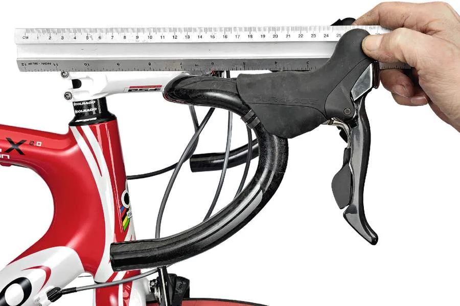
1 Install levers
Ensure your bars are positioned correctly, with the lower flats pointing at an angle somewhere between 0 and 30 degrees below the horizontal. The transition of the drops from the flats will determine whether your bars stay level, or you need to angle them downwards, in order to achieve a comfortably flat hood zone transition. Using a 5mm Allen key, open up the clamp to its maximum by unscrewing the clamp bolt, then slide the lever onto the bar to the desired position. Although the lever body shape has been changed to minimise the risk of damage, you still need to ensure the lever is located on a section of the bar with a matching radius – in other words, neither too high nor too low on the bar.
2 Clamp tight
As with SRAM’s shifting kit featured last month, pay attention to lever offset. Avoid pointing the lever body inwards, which would reduce the amount of offset and increase the possibility of the lever running out of travel and striking the bar. A square ended 5mm Allen key is preferable to a ball-end type, as the latter doesn’t always provide secure engagement. Tighten firmly (about 8nm), to the point where the lever body can’t be moved sideways; a strong sideways punch should only dislodge it slightly, if at all. Shimano Ultegra 6700 levers offer reach adjustment with the use of a rubber insert, available in 5 or 10mm thickness, placed at the top of the lever. These should be included with your new levers or new bike.
3 Ferrule rules
Shimano lever bodies will accept a 5.5 outer diameter ferrule capping the 4mm SIS gear cable outer. The 5mm brake outer can run straight into the body with no 6mm ferrule. Cut the outer cleanly with a good pair of pliers, making sure there are no obstructions, such as a crushed Teflon inner lining or a shard of inner wire. Use a scribe or sharpened spoke to pry open the cut end, after dressing it with a few strokes of a file. To offset a potential increase in friction due to the new aero routing, return spring tension has been slightly increased, so it’s especially important that cable ends are de-burred and securely squared up and butted into their stops. Allow sufficient cable length to enable free movement of the bars.
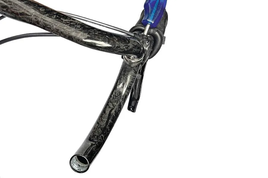
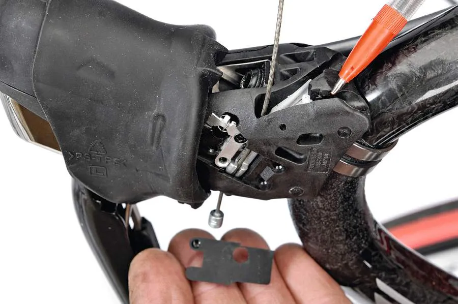
4 Brake cables and lever reach
Installing the brake cables requires the removal of a decorative cover plate made either out of metal (Dura-Ace) or chromed plastic (Ultegra). Remove the small Phillips screw and gently pry off the plate by angling it away, top first. Use more care for the Ultegra cover – it’s a tighter fit and requires more force. Reverse the procedure for installation once you’ve threaded the cable through. A drop or two of oil will make the cables more slippery and lighten the shifting effort while improving shifting accuracy. Dura-Ace 7900 lever reach is adjustable via a small nylon screw adjacent to the brake cable holes. Make sure you can lock up the wheel before the lever comes into contact with the handlebar.
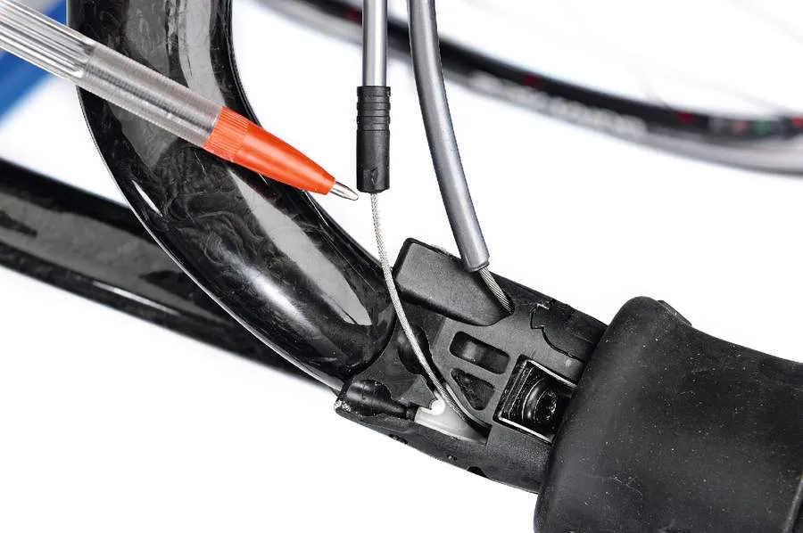
5 Kinky business
Any type of sharp curve or bend put into the cable will be felt through the shifting system, and can cause delayed shifting response and inaccurate gear selection, so Shimano has included a groove which solves this. Notice the protruding cable end – the derailleur cable insert hole is located underneath the lever body, about midway. Before threading, return the cable carrier barrel to its starting position by tapping the release paddle several times; this will line up the cable anchor seat with the opening in the lever body. A small cover on each lever can be removed, as pictured below, to improve access to cables and the shifter mechanism, or aid in threading the cable through. Outside left simply pries off, inside right needs a small screw removed.
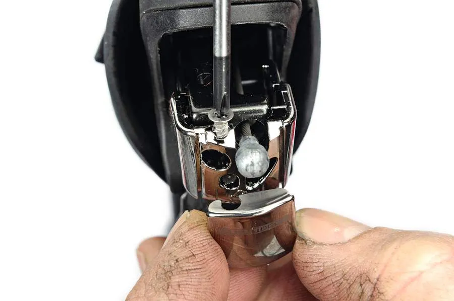
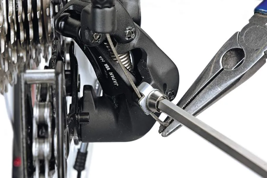
6 Correct anchor routing
This is crucial in getting the right pull ratio out of the derailleur. If in doubt, remove the anchor washer and have a close look. There’ll be a groove on the actuator lever, along with the washer, which will leave you in no doubt which way the cable needs to go. Make sure you’ve noted the washer’s anti-spin tongue and located it correctly. Apply a drop of lube on the barrel adjuster threads and wind it all the way in. String the cable through the last section of outer, having filed the ends square and capped them with ferrules. With the high limit screw set as correctly as possible, use a set of needle nose pliers to pull the cable tight before nipping up the anchor bolt firmly (about 5nm).
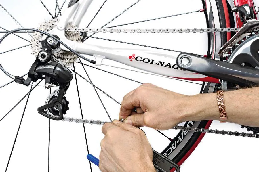
7 Adjust chain length
Shimano’s chain length adjustment technique is a little different to their rivals, but ends up with essentially the same result: a length that will accommodate the large ring and large cog (a combination to be avoided if at all possible), and end up with the derailleur jockey wheels in a more or less vertical position when in the big ring and smallest cog. Check the chain tension in the small ring/small cog combo to make sure it’s not simply flapping about. If it’s borderline loose, you can tighten things up a bit with the B adjustment screw located by the hanger bolt. Designed to adjust the tracking of the upper jockey wheel, turning it clockwise a bit raises the spring tension and tightens the chain a little.
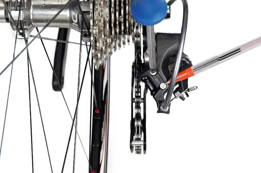
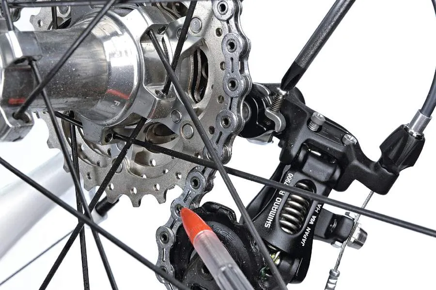
8 Adjust top screws
Set your high and low gear limit screws by eyeballing the position of the jockey wheels relative to the largest (low) and smallest (high) cogs. The upper jockey wheel should line up directly underneath the respective gear, as pictured. On Shimano units the high screw (marked H) is placed above the low screw (marked L). This tends to be the rule on most of their mechs, both front and rear. Ensure the screw is fully butted, preventing any further travel beyond the desired position. Set your front derailleur so that it just clears the chain in the big ring and small cog, with about a 1 or 2mm gap for the outer edge of the cage, and just barely touching the inside of the cage in the small ring and large cog.
9 To B or not to B
As with all rear derailleurs, the accuracy and crispness of shifting response will depend on how closely the upper pulley tracks the cogs. With Shimano, set the B tension screw so that the upper jockey wheel is as close as possible without touching, in the big cog and small ring. (Then check again in the big ring and big cog, for good measure.) Chain length will also influence this adjustment: the shorter the chain length – which will result in more derailleur wind-up – the further away the upper pulley will be from the larger cogs. Removing a link can sometimes help with jockey interference in the largest cog, especially if trying to run a little more than recommended for that mech. Maximum is 27 tooth, 28 in a pinch.
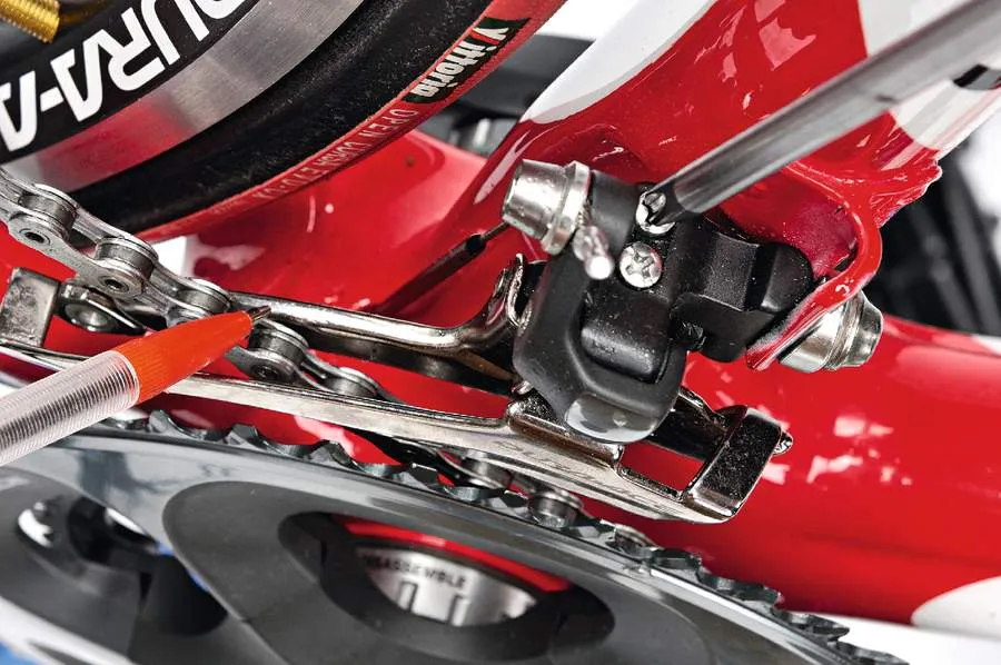
10 Trim, tape and test
Dura-Ace has just one trim adjustment, for the small ring. Actuate the first small click on the large lever, then set the outer edge of the cage so it just barely touches the chain when in the small ring and the smallest cog. On Ultegra, small ring trim is the same as with Dura-Ace, but an additional big ring trim adjustment can be accessed by feathering the small paddle; the inner edge of the cage should barely contact the chain in the big ring and the big cog. Finally, make sure the taping doesn’t interfere with the cable access holes, or mechanical functions of the levers. The cable outers need to be firmly taped against the curve of the bars; a cloth reinforced tape can help stop flex and improve brake response. Test ride and re-adjust as necessary.
