Power meters are increasingly becoming an accepted part of training and racing, but even the cheapest options remain an expensive investment. However, Specialized's patent, filed on 24 June 2016, for a hub-based power-meter could potentially offer a simpler, and hence cheaper, way of measuring your power output.
Gauge your power with strain
To generate power measurements, power is calculated based on the torque applied multiplied by cadence. That torque is measured with strain gauges.
However, strain gauges are sensitive to correct installation and require precise calibration, making them finicky to work with. This increases the cost of the power meter as each is individually calibrated to correlate the force input to the resultant strain measured by the gauges.
Just look at how complicated the process for making a Stages power meter is
Position-based power measurement
The proposed arrangement featured by Specialized in this patent appears to configure the power measurement into a design that could lower manufacturing costs.
As with the strain gauges, the basic principle is the same with a measured deflection correlating to a specific torque. However, this method proposes using an inductive position sensor (instead of a strain gauge) to measure the deflection.
All about torque
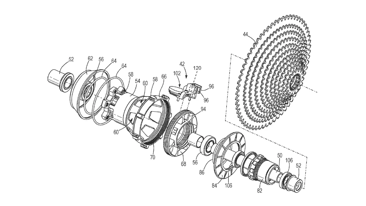
The key component in the proposed configuration is the 'torque element' that connects your torque input (the input from the cassette provided by pedalling) to the torque output (the transfer of torque from the hub shell to the wheel, propelling you forward).
This part is threaded into the hub shell on the drive side and provides the connection between the cassette and the hub shell. That means all driving force is transmitted through this component.
The torque element is constructed so that it deflects when torque is applied through the pedals. It is unclear from the patent how large this deflection might be, but given that inductance transducers are capable of measuring position within the nanometre range, it would not have to be significant.
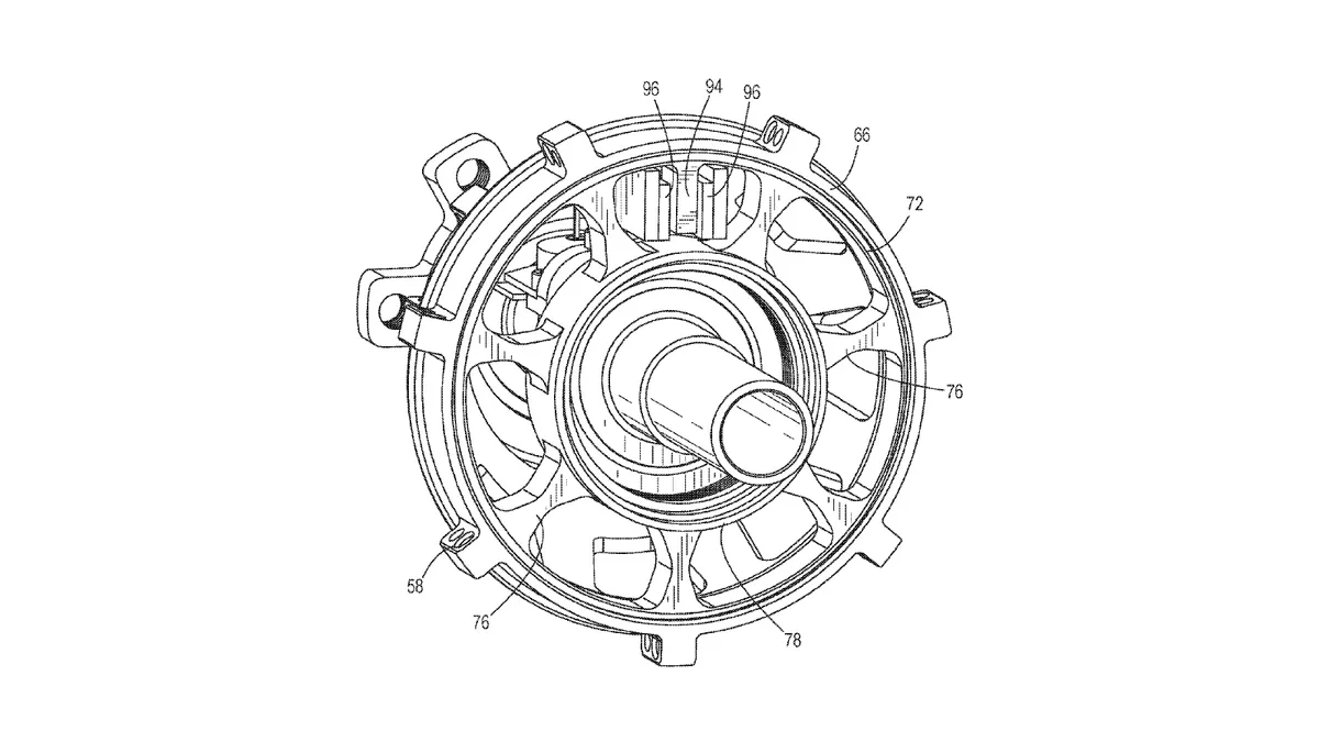
We can understand the inner ring (numbered 78 above if you can make that out) to be the torque input portion. This is connected to the cassette body via a standard freehub assembly. The torque output portion (72) is connected to the hub shell (66) providing the driving force to the wheel.
The input and output portion are connected via 'torque spokes' (76) that transmit your driving force across the torque element. Torque input will result in the inner ring (78) rotating slightly relative to the outer ring (72). Measuring this deflection allows the torque to be inferred.
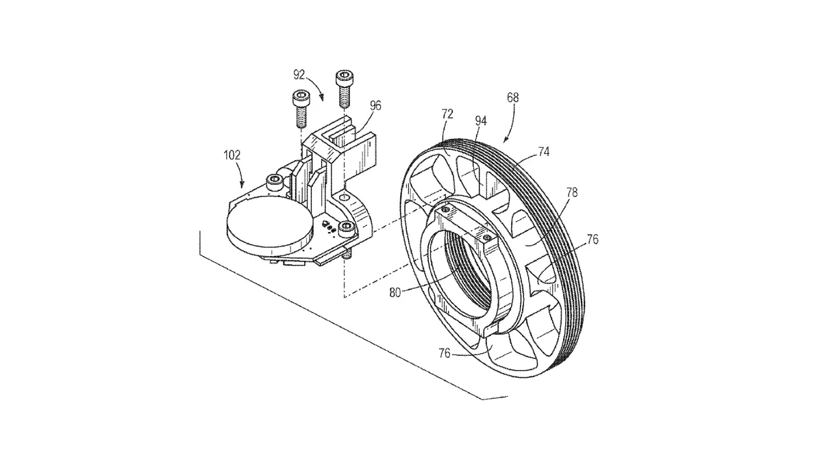
The inductive sensor (numbered 102 below) is mounted on the inner ring (78). A conductive displacement indicator (94) extends from the outer ring (72) allowing the relative rotation of the torque input and output to be measured.
Measuring deflection, calculating torque
The Specialized patent suggests using an inductive position sensor mounted on each side of the tab (94). This differential configuration would be slightly more costly to implement, but should result in better temperature stability, better accuracy and long-term stability.
It is unclear from the documentation how the deflection properties of the torque element are determined. It seems it would be straightforward to compute the characteristics of the element.
We imagine that manufacturing tolerances would be fine enough that the parts could be consistent enough across batches not to require individual characterisation.
Indeed, assuming the properties of the sensors are also well characterised, the differential arrangement of the sensors combined with a well-characterised torque element should allow for installation of the sensors without having to calibrate each unit individually. It is this that would be key for saving costs.
Of course, this is speculation on our part, but the fact is that strain gauges will always require calibration. The sensor arrangement described here could remove the need for this.
Auto-zeroing
One additional issue with power meters is that the zero-offset can change depending on environmental conditions. That means the power meter may provide a false power reading i.e. it is not at zero when there is no power.
Thus, it’s generally advisable to zero the power meter with no load applied before heading out for your ride.
Specialized expands on that concept. The patent suggests the hub can be set up to detect when the freewheel is coasting i.e. no load is applied. The power meter can then automatically zero the power meter on the fly to ensure it stays calibrated throughout your ride.
Will it happen?
We're unclear how reliable inductance sensors can be and how much variability there is between sensors. We imagine, given that this patent exists, that they could provide a viable means of measuring power. Whether this can be done at reduced costs remains to be seen however.
We would also add that hub-based power meters don't provide a huge degree of flexibility. Being built into a wheel means no power measurement if you want to run a different wheelset for a particular event, or to suit the weather. Whether this would be a problem depends on your needs. Equally, we could see this technology being adapted to crank-based systems, which would provide the flexibility inherent to other power meters
In any case, it's interesting to see thought being put into different methods for measuring power, and we look forward to seeing whether anything based on this technology shows up in the future.